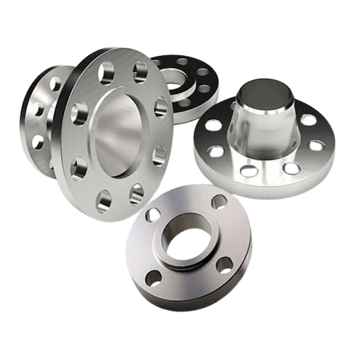
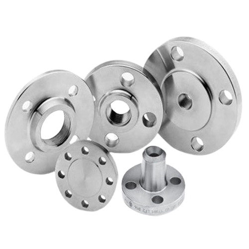
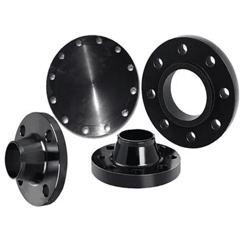
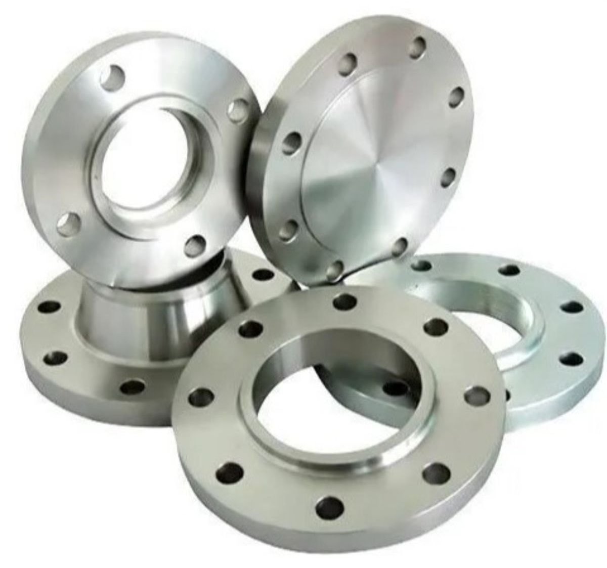
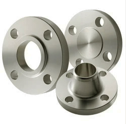
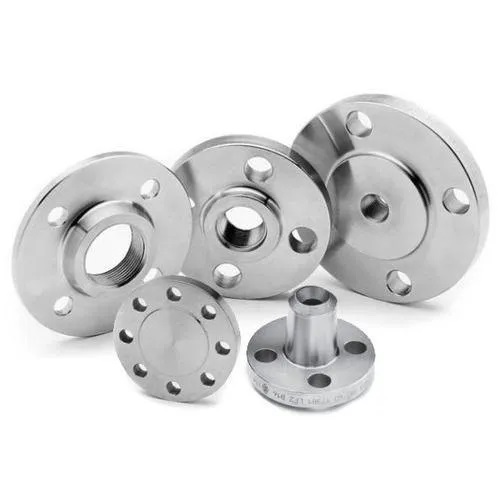
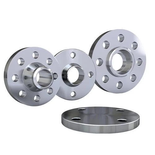
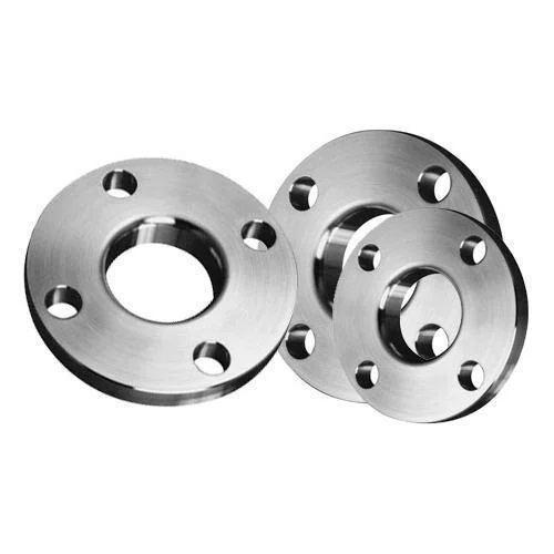
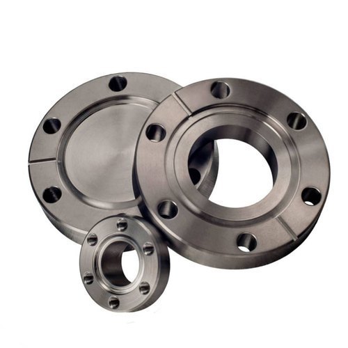
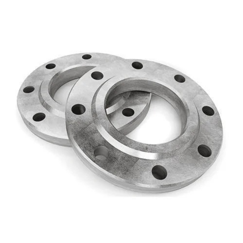
At Ratnadeep Steel & Engg. Co., we specialize in the manufacturing and supply of high-quality flanges designed to meet a wide range of industrial applications. Our extensive product range includes:
Slip-On (SO) Flanges
Weld Neck (WN) Flanges
Plate (PL) Flanges
Socket Weld (SW) Flanges
Orifice Flanges
Ring Joint Flanges
Blind (BL) Flanges
Lap Joint (LJ) Flanges
Threaded (TH) Flanges
Spectacle Blinds
Long Weldneck Flanges
Our flanges are available in a variety of connection types, including bolted, welded, and threaded, depending on the specific demands of your project.
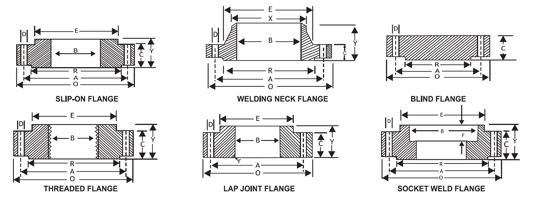
Note: Metric values are direct conversion from Inches table of B16.5.
Flanges except Lap Joint will be furnished with (1.6 mm) raised face, Which is included in “Thickness” (C) and Length Through Hub (Y).
DIMENSIONS OF CLASS 900 FLANGES AS PER B 16.5
▼
Click to expand table
Nominal Pipe Size
Flange Dia O
Dia of Bolt Circle A
Dia of Bolt Holes
No. of Holes
Thk. of Flange tf
Dia of Hub C
Length through Hub
Dia Bore
Dia of R/F F
Depth of Socket F
Pipe Dia X
S/O & SW E
W/N
L/J Y
S/O & SW
L/J B
E
Y
Y
B
B
15
120.7
82.6
15.9
4
22.4
38.1
28.6
57.2
28.6
22.4
22.9
34.9
9.5
21.33
20
130.0
88.9
15.9
4
25.4
47.8
31.8
61.9
31.8
27.7
28.2
42.9
11.1
26.67
25
149.4
101.6
15.9
4
28.4
54.0
34.9
66.7
34.9
34.5
35.0
50.8
12.7
33.40
32
158.8
111.1
19.0
4
30.2
63.5
38.1
69.9
38.1
43.2
43.7
63.5
14.3
42.16
40
177.8
123.8
19.0
4
31.8
69.9
41.3
73.0
41.3
49.5
50.0
73.0
15.9
48.26
50
203.2
139.7
22.2
8
35.1
84.1
47.6
82.6
47.6
62.0
62.5
92.1
17.5
60.31
65
228.6
165.1
22.2
8
38.1
100.0
53.8
88.9
53.8
74.7
75.4
104.8
19.0
73.02
80
254.0
184.1
22.2
8
41.1
117.5
57.2
95.2
57.2
90.7
91.4
127.0
20.6
88.90
100
279.4
209.6
25.4
8
47.8
152.4
63.5
108.0
63.5
116.1
116.8
157.2
–
114.30
125
342.9
241.3
28.6
8
53.8
188.9
69.9
117.5
69.9
143.8
144.5
185.7
–
141.30
150
381.0
279.4
28.6
12
57.2
223.2
76.2
127.0
76.2
170.1
171.4
215.9
–
168.27
200
444.5
342.9
31.8
12
63.5
273.0
88.9
142.9
88.9
221.5
222.2
269.9
–
219.07
250
520.7
406.4
34.9
12
69.9
342.9
101.6
158.8
101.6
276.3
277.4
323.8
–
273.05
300
584.2
482.6
34.9
16
79.2
400.0
114.3
174.6
114.3
327.1
328.2
381.0
–
323.85
350
647.7
533.4
38.1
16
85.9
431.8
127.0
184.1
127.0
359.1
360.2
412.7
–
355.60
400
711.2
596.9
41.3
16
88.9
495.3
139.7
200.0
139.7
410.5
411.2
469.9
–
406.40
450
774.7
635.0
41.3
20
101.6
548.1
152.4
215.9
152.4
461.8
462.3
533.4
–
457.00
500
838.2
692.2
44.5
20
108.0
609.6
165.1
222.2
165.1
513.1
514.3
584.2
–
508.00
600
965.2
812.8
50.8
20
123.8
717.5
190.5
247.6
190.5
615.9
615.9
692.1
–
609.60
DIMENSIONS OF CLASS 1500 FLANGES AS PER B 16.5
▼
Click to expand table
Nominal Pipe Size
Flange Dia O
Dia of Bolt Circle A
Dia of Bolt Holes
No. of Holes
Thk. of Flange tf
Dia of Hub C
Length through Hub
Dia Bore
Dia of R/F F
Depth of Socket
Pipe Dia X
S/O & SW E
W/N
L/J Y
S/O & SW
L/J B
E
Y
Y
B
B
15
120.6
82.5
22.2
4
22.2
38.1
31.7
60.3
31.7
22.3
22.8
34.9
9.5
21.33
20
130.2
88.9
22.2
4
25.4
44.4
34.9
69.8
34.9
27.7
28.1
42.9
11.1
26.67
25
149.2
101.6
25.4
4
28.6
52.4
41.3
73.0
41.3
34.5
35.0
50.8
12.7
33.40
32
158.7
111.1
25.4
4
28.6
63.5
41.3
73.0
41.3
43.2
43.6
63.5
14.2
42.16
40
177.8
123.8
28.6
4
31.8
69.8
44.4
82.5
44.4
49.5
50.0
73.0
15.8
48.26
50
215.9
165.1
25.4
8
38.1
104.8
57.1
101.6
57.1
62.0
62.0
92.1
17.4
60.31
65
244.5
190.5
28.6
8
41.3
123.8
63.5
104.8
63.5
74.7
75.4
104.8
19.0
73.02
80
266.7
203.2
31.7
8
47.6
133.3
73.0
117.5
73.0
90.7
91.7
127.0
–
86.90
100
311.1
241.3
34.9
8
54.0
161.9
90.5
123.0
90.4
116.1
116.5
157.2
–
114.30
125
374.6
292.1
41.3
8
72.0
196.8
104.8
155.6
104.8
143.8
144.5
185.7
–
141.30
150
392.7
317.5
38.1
12
82.6
228.6
119.1
171.4
119.1
170.7
171.4
215.9
–
168.27
200
482.6
393.7
44.4
12
92.1
222.1
142.9
212.7
142.8
221.5
222.2
269.9
–
219.07
250
584.2
482.6
50.8
12
107.9
368.3
158.7
254.0
177.8
276.3
277.3
323.8
–
273.05
300
673.1
571.5
54.0
16
123.8
450.8
181.0
282.6
218.9
327.1
328.1
381.0
–
323.85
DIMENSIONS OF CLASS 2500 FLANGES AS PER B 16.5
▼
Click to expand table
Nominal Pipe Size
Flange Dia O
Dia of Bolt Circle A
Dia of Bolt Holes
No. of Holes
Thk. of Flange tf
Dia of Hub C
Length through Hub
Dia Bore
Dia of R/F F
Depth of Socket
Pipe Dia X
S/O & SW E
W/N
L/J Y
S/O & SW
L/J B
E
Y
Y
B
B
15
133.3
88.9
22.2
4
30.2
42.9
39.7
73.0
39.7
22.3
22.3
34.9
–
21.33
20
139.7
95.2
22.2
4
31.7
50.8
42.9
79.4
42.9
27.7
27.7
42.9
–
26.67
25
158.7
107.9
25.4
4
34.9
57.1
47.7
88.9
47.7
34.5
34.5
50.8
–
33.40
32
184.1
130.2
28.6
4
38.1
73.0
52.4
95.2
52.4
43.2
43.2
63.5
–
42.16
40
203.2
146.0
31.7
4
44.4
79.4
60.3
111.1
60.3
49.5
49.5
73.0
–
48.26
50
234.9
171.4
28.6
8
50.8
95.2
69.8
127.0
69.8
62.4
62.0
92.1
–
60.31
65
266.7
196.8
31.7
8
57.1
114.3
79.4
142.9
79.4
74.7
74.7
104.8
–
73.02
80
304.8
228.6
34.9
8
66.7
133.3
92.1
168.3
92.1
90.7
90.7
127.0
–
88.90
100
355.6
273.0
41.3
8
76.2
165.1
107.9
190.5
107.9
116.1
116.1
157.2
–
114.30
125
416.1
323.8
47.6
8
92.1
209.2
130.0
228.6
130.0
143.8
143.8
185.7
–
141.30
150
482.6
368.3
54.0
8
107.9
234.9
152.4
273.0
152.4
170.7
170.7
215.1
–
168.27
200
652.4
438.1
56.0
12
127.0
304.8
177.8
317.5
177.8
221.5
221.5
269.9
–
219.07
250
673.1
539.7
66.7
12
165.1
374.6
226.6
419.1
228.6
276.3
276.3
323.8
–
273.05
300
762.0
619.1
73.0
12
184.1
441.3
254.9
463.5
254.0
327.1
327.1
381.0
–
323.85
Note: Metric values are direct conversion from Inches table of B16.5.
RF THickness 6.3 mm Extra to be provided (Except Lap Joint Flange & FF Flanges)..
FLANGES CLASS – PN10 / PN16 / PN25 / PN40
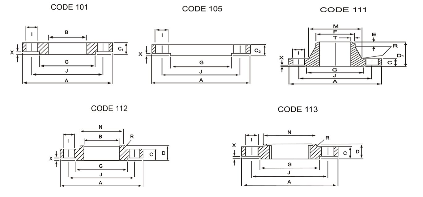
DIMENSIONS OF BS4504 PN10 FLANGES
▼
Click to expand table
Nom. Size NB
Flange
Raised Face
Boss
Drilling
Bolting
Neck
Bore Diameter
A
C
C1
C2
D
D1
G
X
N
No.
I
J
M
F
E
R
T
B
10
90
14
14
14
20
35
40
2
30
4
14
60
M12
28
17.2
6
3
1.8
18.0
15
95
14
14
14
20
35
45
2
35
4
14
65
M12
32
21.3
6
3
2.0
22.0
20
105
16
16
16
24
38
58
2
45
4
14
75
M12
39
26.9
6
4
2.3
27.5
25
115
16
16
16
24
38
68
2
52
4
14
85
M12
46
33.4
6
4
2.6
34.5
32
140
16
18
16
26
40
78
2
60
4
18
100
M16
56
42.2
6
5
2.6
43.0
40
150
16
18
16
26
42
88
3
70
4
18
110
M16
64
48.3
7
5
2.6
49.5
50
165
18
20
18
28
45
102
3
84
4
18
125
M16
74
60.3
8
5
2.9
61.6
65
185
18
20
18
32
45
122
3
104
4/8
18
145
M16
92
73.0
10
6
2.9
74.0
80
200
20
20
20
34
50
138
3
118
8
18
160
M16
110
88.9
10
6
3.2
90.5
100
220
20
22
20
40
52
162
3
140
8
18
180
M16
130
114.3
12
6
3.6
116.0
125*
250
22
22
22
44
55
188
3
168
8
18
210
M16
158
141.3
12
6
4.0
142.5
150
285
22
24
22
44
55
212
3
195
8
22
240
M20
184
168.3
12
8
4.5
170.5
200
340
24
24
24
44
62
268
3
246
8
22
295
M20
234
219.1
16
8
5.6
221.5
250
395
26
26
26
46
68
320
3
298
12
22
350
M20
288
273.0
16
10
6.3
276.5
300
445
26
28
26
46
68
370
4
350
12
22
400
M20
342
323.9
16
10
7.1
327.6
350
505
26
28
28
53
68
430
4
400
16
22
460
M20
390
355.6
16
10
7.1
359.0
400
565
26
32
28
57
72
482
4
459
16
26
515
M24
440
406.4
16
10
7.1
411.0
450
615
28
36
28
63
72
532
4
502
20
26
565
M24
488
457.0
16
12
7.1
462.0
500
670
28
38
28
67
75
585
4
559
20
26
620
M24
540
508.0
16
12
7.1
513.5
600
780
28
42
28
75
80
685
5
658
20
30
725
M27
640
610.0
18
12
7.1
616.5
700
895
30
–
38
–
80
800
5
–
24
30
840
M27
746
711.0
18
12
8.0
–
800
1015
32
–
32
–
90
905
5
–
24
33
950
M30
848
813.0
18
12
8.0
–
900
1115
34
–
34
–
95
1005
5
–
28
33
1050
M30
948
914.0
20
12
10.0
–
1000
1230
34
–
34
–
95
1110
5
–
28
36
1160
M33
1050
1016.0
20
12
10.0
–
1200
1455
38
–
38
–
115
1330
5
–
32
39
1380
M36
1256
1220.0
25
12
11.0
–
1400
1675
42
–
–
–
120
1535
5
–
36
42
1590
M39
1460
1420.0
25
12
12.0
–
1600
1915
46
–
–
–
130
1760
5
–
40
48
1820
M45
1666
1620.0
25
12
14.0
–
1800
2115
50
–
–
–
140
1960
5
–
44
48
2020
M45
1866
1820.0
30
15
15.0
–
2000
2325
54
–
–
–
150
2170
5
–
48
48
2230
M45
2070
2020.0
30
15
16.0
–
2200
2550
58
–
–
–
160
2370
6
–
52
56
2440
M52
2275
2220.0
35
15
–
–
2400
2760
62
–
–
–
170
2570
6
–
56
56
2650
M52
2478
2420.0
35
15
–
–
2600
2960
65
–
–
–
180
2780
6
–
60
56
2850
M52
2680
2620.0
35
18
–
–
2800
3180
70
–
–
–
190
3000
6
–
64
56
3070
M52
2882
2820.0
40
18
–
–
3000
3405
75
–
–
–
200
3210
6
–
68
62
3290
M56
3085
3020.0
40
18
–
–
Note:
* Care should be taken with these sizes as the pipe o.d. does not relate to normal stainless steel dimensions.
1. Weldnecks (Code 111) are bored to suit schedule of pipework used.
2. Code 105 flanges are supplied flat faced unless otherwise requested by the purchaser.
3. For information sizes NB 10 to DN150 use PN16 dimensions.
DIMENSIONS OF BS4504 PN16 FLANGES
▼
Click to expand table
Nom. Size NB
Flange
Raised Face
Boss
Drilling
Bolting
Neck
Bore Diameter
A
C
C1
C2
D
D1
G
X
N
No.
I
J
M
F
E
R
T
B
10
90
14
14
14
20
35
40
2
30
4
14
60
M12
28
17.2
6
3
1.8
18.0
15
95
14
14
14
20
35
45
2
35
4
14
65
M12
32
21.3
6
3
2.0
22.0
20
105
16
16
16
24
38
58
2
45
4
14
75
M12
39
26.9
6
4
2.3
27.5
25
115
16
16
16
24
38
68
2
52
4
14
85
M12
46
33.4
6
4
2.6
34.5
32
140
16
18
16
26
40
78
2
60
4
18
100
M16
56
42.2
6
5
2.6
43.0
40
150
16
18
16
26
42
88
3
70
4
18
110
M16
64
48.3
7
5
2.6
49.5
50
165
18
20
18
28
45
102
3
84
4
18
125
M16
74
60.3
8
5
2.9
61.5
65
185
18
20
18
32
45
122
3
104
4/8
18
145
M16
92
73.0
10
6
2.9
74.0
80
200
20
20
20
34
50
138
3
118
8
18
160
M16
110
88.9
10
6
3.2
90.5
100
220
20
22
20
40
52
162
3
140
8
18
180
M16
130
114.3
12
6
3.6
116.0
125*
250
22
22
22
44
55
188
3
168
8
18
210
M16
158
141.3
12
6
4.0
142.5
150
285
22
24
22
44
55
212
3
195
8
22
240
M20
184
168.3
12
8
4.5
170.5
200
340
24
26
24
44
62
268
3
246
12
22
295
M20
234
219.1
16
8
5.6
221.5
250
405
26
29
26
46
70
320
3
298
12
26
355
M24
288
273.0
16
10
6.3
276.5
300
460
28
32
28
46
78
378
4
350
12
26
410
M24
342
323.9
16
10
7.1
327.6
350
520
30
35
30
57
82
438
4
400
16
26
470
M24
390
355.6
16
10
8.0
359.0
400
580
32
38
32
63
85
490
4
456
16
30
525
M27
444
406.4
16
10
8.0
411.0
450
640
34
42
36
63
87
550
4
502
20
30
585
M27
490
457.0
16
12
8.0
462.0
500
715
34
46
36
73
90
610
4
559
20
33
650
M30
546
508.0
16
12
8.0
513.5
600
840
36
52
44
83
95
725
5
658
20
36
770
M33
650
610.0
18
12
8.8
616.5
700
910
36
60
48
83
100
795
5
760
24
36
840
M33
750
711.0
18
12
8.6
–
800
1025
38
68
52
90
105
900
5
864
24
39
950
M36
848
813.0
20
12
10.0
–
900
1125
40
76
58
94
110
1000
5
968
28
39
1050
M39
948
914.0
20
12
10.0
–
1000
1255
42
84
64
100
120
1115
5
1072
28
42
1170
M39
1056
1016.0
22
12
10.0
–
1200
1485
48
98
76
–
130
1330
5
–
32
48
1390
M45
1260
1220.0
30
12
12.5
–
1400
1685
52
–
–
–
145
1530
5
–
36
48
1590
M45
1465
1420.0
30
12
14.2
–
1600
1930
58
–
–
–
160
1750
5
–
40
56
1820
M52
1668
1620.0
35
12
16.0
–
1800
2130
62
–
–
–
170
1950
5
–
44
56
2020
M52
1870
1820.0
35
15
17.5
–
2000
2435
66
–
–
–
190
2150
5
–
48
62
2230
M56
2072
2020.0
40
15
20.0
–
Note: * Care should be taken with these sizes as the pipe o.d. does not relate to normal stainless steel dimensions.
1. Weldnecks (Code 111) are bored to suit schedule of pipework used.
2. Code 105 flanges are supplied flat faced unless otherwise requested by the purchaser.
DIMENSIONS OF BS4504 PN25 FLANGES
▼
Click to expand table
Nom. Size NB
Flange
Raised Face
Boss
Drilling
Bolting
Neck
Bore Diameter
A
C
C1
C2
D
D1
G
X
N
No.
I
J
M
F
E
R
T
B
10
90
16
14
16
22
35
40
2
30
4
14
60
M12
28
17.2
6
3
1.8
18.0
15
95
16
14
16
22
38
45
2
35
4
14
65
M12
32
21.3
6
3
2.0
22.0
20
105
18
16
18
26
40
58
2
45
4
14
75
M12
40
26.9
6
4
2.3
27.5
25
115
18
16
18
28
40
68
2
52
4
14
85
M12
46
33.4
6
4
2.6
34.5
32
140
18
18
18
30
42
78
2
60
4
18
100
M16
56
42.2
7
5
2.6
43.0
40
150
18
18
18
32
45
88
3
70
4
18
110
M16
64
48.3
7
5
2.9
49.5
50
165
20
20
20
34
48
102
3
84
4
18
125
M16
74
60.3
8
5
2.9
61.5
65
185
22
22
22
38
52
122
3
104
8
18
145
M16
92
73.0
10
6
2.9
74.0
80
200
24
24
24
40
58
138
3
118
8
18
160
M16
110
88.9
12
6
3.2
90.5
100
235
24
26
24
44
65
162
3
145
8
22
190
M20
134
114.3
12
6
3.6
116.0
125*
270
26
28
26
48
68
188
3
170
8
26
220
M24
162
141.3
12
6
4.0
142.5
150
300
28
30
28
52
75
218
3
200
8
26
250
M24
190
168.3
12
8
4.5
170.5
200
360
30
32
30
52
80
278
3
256
12
26
310
M24
244
219.1
16
8
6.3
221.5
250
425
32
35
32
60
88
335
3
310
12
30
370
M27
296
273.0
18
10
7.1
276.5
300
485
34
38
34
67
92
395
4
364
16
30
430
M27
350
323.9
18
10
8.0
327.5
350
555
38
42
38
72
100
450
4
418
16
33
490
M30
398
355.6
20
10
8.0
359.5
400
620
40
46
40
78
110
505
4
472
16
36
550
M33
452
406.4
20
10
8.8
411.0
450
670
42
50
44
84
110
555
4
520
20
36
600
M33
500
457.0
20
12
8.8
462.0
500
730
44
56
45
90
125
615
4
580
20
36
660
M33
558
508.0
20
12
10.0
513.5
600
845
46
68
54
100
125
720
5
684
20
39
770
M36
660
610.0
20
12
11.0
616.5
700
960
46
–
–
–
125
820
5
–
24
42
875
M39
760
711.0
20
12
12.5
–
800
1085
50
–
–
–
135
930
5
–
24
48
990
M45
864
813.0
22
12
14.2
–
900
1185
54
–
–
–
145
1030
5
–
28
48
1090
M45
968
914.0
24
12
16.0
–
1000
1320
58
–
–
–
155
1140
5
–
28
56
1210
M52
1070
1016.0
24
12
17.5
–
1200
1530
–
–
–
–
–
1350
5
–
32
56
1420
M52
–
1220.0
–
12
12.5
–
1400
1755
–
–
–
–
–
1560
5
–
36
62
1640
M56
–
1420.0
–
12
14.2
–
1600
1975
–
–
–
–
–
1780
5
–
40
62
1860
M56
–
1620.0
–
15
16.0
–
1800
2185
–
–
–
–
–
1985
5
–
44
70
2070
M64
–
1820.0
–
15
17.5
–
2000
2425
–
–
–
–
–
2210
5
–
48
70
2300
M64
–
2020.0
–
15
20.0
–
Note:
* Care should be taken with these sizes as the pipe o.d. does not relate to normal stainless steel dimensions.
1. Weldnecks (Code 111) are bored to suit schedule of pipework used.
2. Code 105 flanges are supplied flat faced unless otherwise requested by the purchaser.
3. For information sizes NB 10 to NB 150 use PN40 dimensions.
DIMENSIONS OF BS4504 PN40 FLANGES
▼
Click to expand table
Nom. Size NB
Flange
Raised Face
Boss
Drilling
Bolting
Neck
Bore Diameter
A
C
C1
C2
D
D1
G
X
N
No.
I
J
M
F
E
R
T
B
10
90
16
14
16
22
35
40
2
30
4
14
60
M12
28
17.2
6
3
1.8
18.0
15
95
16
14
16
22
38
45
2
35
4
14
65
M12
32
21.3
6
3
2.0
22.0
20
105
18
16
18
26
40
58
2
45
4
14
75
M12
40
26.9
6
4
2.3
27.5
25
115
18
16
18
28
40
68
2
52
4
14
85
M12
46
33.4
6
4
2.6
34.5
32
140
18
18
18
30
42
78
2
60
4
18
100
M16
56
42.2
6
5
2.6
43.5
40
150
18
18
18
32
45
88
3
70
4
18
110
M16
64
48.3
7
5
2.6
49.5
50
165
20
20
20
34
48
102
3
84
4
18
125
M16
74
60.3
8
5
2.9
61.5
65
185
22
22
22
38
52
122
3
104
8
18
145
M16
92
76.1
10
6
2.9
77.5
80
200
24
24
24
40
58
138
3
118
8
18
160
M16
110
88.9
12
6
3.2
90.5
100
235
24
26
24
44
65
162
3
145
8
22
190
M20
134
114.3
12
6
3.6
116.0
125*
270
26
28
26
48
68
188
3
170
8
26
220
M24
162
141.3
12
6
4.0
142.5
150
300
28
30
28
52
75
218
3
200
8
26
250
M24
190
168.3
12
8
4.5
170.5
200
375
34
36
36
52
88
285
3
260
12
30
320
M27
244
219.1
16
8
6.3
221.5
250
450
38
42
38
60
105
345
3
312
12
33
385
M30
306
273.0
18
10
7.1
276.5
300
515
42
48
42
67
115
410
4
380
16
33
450
M30
362
323.9
18
10
8.0
327.5
350
580
46
54
46
72
125
465
4
424
16
36
510
M33
408
355.6
20
10
8.8
359.5
400
660
50
60
50
78
135
535
4
478
16
33
585
M36
462
406.4
20
10
11.0
411.0
450
685
50
66
54
84
135
560
4
522
20
39
610
M36
500
457.0
20
12
12.5
462.0
500
755
52
72
56
90
140
615
4
576
20
42
670
M39
562
508.0
20
12
14.2
513.5
600
890
60
84
70
100
150
735
5
686
20
48
795
M45
666
610.0
20
12
16.0
616.5
Note:
* Care should be taken with these sizes as the pipe o.d. does not relate to normal stainless steel dimensions.
1. Weldnecks (Code 111) are bored to suit schedule of pipework used.
2. Code 105 flanges are supplied flat faced unless otherwise requested by the purchaser.
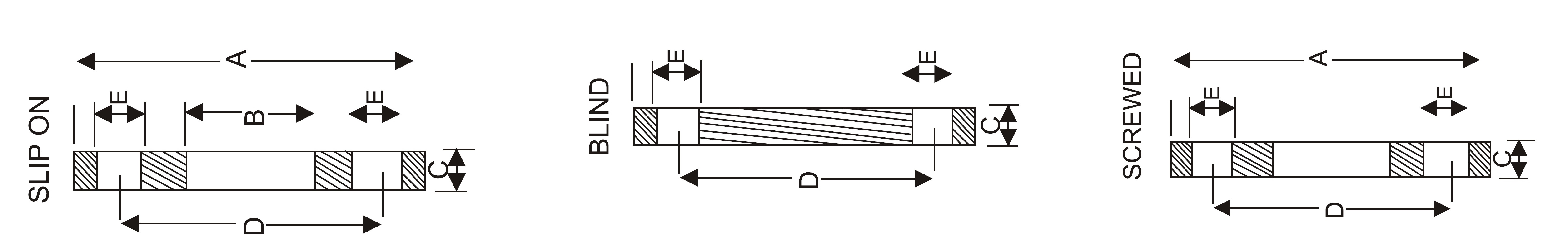
British Standard – 10
Table D : For working steam pressure upto 50 lbs per sq. inch.
▼
Click to expand table
Nominal pipe size
O.D. of Pipe
Dia. of Flange
Dia. Of Bolt Circle
No. of Bolt
Dia. of Bolt
Thickness
1/2″
27/32″
3.34″
2.5/8″
4
1/2″
3/16″
3/4″
1.1/16″
4″
2.7/8″
4
1/2″
3/16″
1″
1.11/32″
4.1/2″
3.1/4″
4
1/2″
3/16″
1.1/4″
1.11/16″
4.3/4″
3.7/16″
4
1/2″
1/4″
1.1/2″
1.28/32″
5.1/4″
3.7/8″
4
1/2″
1/4″
2″
2.3/8″
6″
4.1/2″
4
5/8″
5/16″
2.1/2″
3″
6.1/2″
5″
4
5/8″
5/16″
3″
3.1/2″
7.1/4″
5.3/4″
4
5/8″
3/8″
3.1/2″
4″
8″
6.1/2″
4
5/8″
3/8″
4″
4.1/2″
8.1/2″
7″
4
5/8″
3/8″
5″
5.1/2″
10″
8.1/4″
8
5/8″
1/2″
6″
6.12″
11″
9.1/4″
8
5/8″
1/2″
7″
7.1/2″
12″
10.1/4″
8
5/8″
1/2″
8″
8.5/8″
13.1/4″
11.1/2″
8
5/8″
1.1/2″
9″
9.5/8″
14.1/2″
12.3/4″
8
5/8″
5/8″
10″
10.3/4″
16″
14″
8
3/4″
5/8″
12″
12.3/4″
18″
16″
8
3/4″
5/8″
14″
14″
20.3/4″
18.1/2″
12
7/8″
3/4″
16″
16″
22.3/4″
20.1/2″
12
7/8″
3/4″
18″
18″
25.1/4″
23″
12
7/8″
7/8″
20″
20″
27.3/4″
25.1/4″
16
7/8″
1″
24″
24″
32.1/2″
29.3/4″
16
1″
1.1/8″
Table E : For working steam pressure upto 50 lbs and upto 100 per sq. inch.
▼
Click to expand table
Nominal pipe size
Dia. of Flange
Dia. Of Bolt Circle
No. of Bolt
Dia. of Bolt
Thickness
1/2″
3.34″
2.5/8″
4
1/2″
1/4″
3/4″
4″
2.7/8″
4
1/2″
1/4″
1″
4.1/2″
3.1/4″
4
1/2″
9/32″
1.1/4″
4.3/4″
3.7/16″
4
1/2″
5/16″
1.1/2″
5.1/4″
3.7/8″
4
1/2″
11/32″
2″
6″
4.1/2″
4
5/8″
3/8″
2.1/2″
6.1/2″
5″
4
5/8″
13/32″
3″
7.1/4″
5.3/4″
4
5/8″
7/16″
3.1/2″
8″
6.1/2″
8
5/8″
15/32″
4″
8.1/2″
7″
8
5/8″
1/2″
5″
10″
8.1/4″
8
5/8″
9/16″
6″
11″
9.1/4″
8
3/4″
11/16″
7″
12″
10.1/4″
8
3/4″
3/4″
8″
13.1/4″
11.1/2″
8
3/4″
3/4″
9″
14.1/2″
12.3/4″
12
3/4″
13/16″
10″
16″
14″
12
3/4″
7/8″
12″
18″
16″
12
7/8″
1″
14″
20.3/4″
18.1/2″
12
7/8″
1″
16″
22.3/4″
20.1/2″
12
7/8″
1″
18″
25.1/4″
23″
16
7/8″
1.1/8″
20″
27.3/4″
25.1/4″
16
7/8″
1.1/4″
24″
32.1/2″
29.3/4″
16
1.1/8″
1.1/2″
Table F : For working steam pressure upto 100 lbs and upto 150 per sq. inch.
▼
Click to expand table
Nominal pipe size
Dia. of Flange
Dia. Of Bolt Circle
No. of Bolt
Dia. of Bolt
Thickness
1/2″
3.34″
2.5/8″
4
1/2″
3/8″
3/4″
4″
2.7/8″
4
1/2″
3/8″
1″
4.3/4″
3.7/16″
4
5/8″
3/8″
1.1/4″
5.1/4″
3.7/8″
4
5/8″
1/2″
1.1/2″
5.1/2″
4.1/8″
4
5/8″
1/2″
2″
6.1/2″
5″
4
5/8″
5/8″
2.1/2″
7.1/4″
5.3/4″
8
5/8″
5/8″
3″
8″
6.1/2″
8
5/8″
5/8″
3.1/2″
8.1/2″
7″
8
5/8″
3/4″
4″
9″
7.1/2″
8
5/8″
3/4″
5″
11″
9.1/4″
8
3/4″
7/8″
6″
12″
10.1/4″
12
3/4″
7/8″
7″
13.1/4″
11.1/2″
12
3/4″
7/8″
8″
14.1/2″
12.3/4″
12
3/4″
1″
9″
16″
14″
12
7/8″
1″
10″
17″
15″
12
7/8″
1″
12″
19.1/4″
17.1/4″
16
7/8″
1.1/8″
14″
21.3/4″
19.1/2″
16
1″
1.1/4″
16″
24″
21.3/4″
20
1″
1.1/4″
18″
26.1/2″
24″
20
1.1/8″
1.3/8″
20″
29″
26.1/2″
24
1.1/8″
1.1/2″
24″
33.1/2″
30.3/4″
24
1.1/8″
1.5/8″
Table H : For working steam pressure upto 150 lbs and upto 250 per sq. inch.
▼
Click to expand table
Nominal pipe size
Dia. of Flange
Dia. Of Bolt Circle
No. of Bolt
Dia. of Bolt
Thickness
1/2″
4.1/2″
3.1/4″
4
5/8″
1/2″
3/4″
4.1/2″
3.1/4″
4
5/8″
1/2″
1″
4.3/4″
3.7/16″
4
5/8″
9/16″
1.1/4″
5.1/4″
3.7/8″
4
5/8″
11/16″
1.1/2″
5.1/2″
4.1/8″
4
5/8″
11/16″
2″
6.1/2″
5″
4
5/8″
3/4″
2.1/2″
7.1/4″
5.3/4″
8
5/8″
3/4″
3″
8″
6.1/2″
8
5/8″
7/8″
3.1/2″
8.1/2″
7″
8
5/8″
7/8″
4″
9″
7.1/2″
8
5/8″
1″
5″
11″
9.1/4″
8
3/4″
1.1/8″
6″
12″
10.1/4″
12
3/4″
1.1/8″
7″
13.1/4″
11.1/2″
12
3/4″
1.1/4″
8″
14.1/2″
12.3/4″
12
3/4″
1.1/4″
9″
16″
14″
12
7/8″
1.3/8″
10″
17″
15″
12
7/8″
1.3/8″
12″
19.1/4″
17.1/4″
16
7/8″
1.1/2″
14″
21.3/4″
19.1/2″
16
1″
1.5/8″
16″
24″
21.3/4″
20
1″
1.3/4″
18″
26.1/2″
24″
20
1.1/8″
1.7/8″
20″
29″
26.1/2″
24
1.1/8″
2″
24″
33.1/2″
30.3/4″
24
1.1/4″
2.1/4″
Request a Quote
Looking for high-performance Flanges? Get in touch with us today.